2023
2021

Tau Boo b
2021/08 – Artist view of the hot Jupiter Tau Boo B orbiting its host star ©Harvard-CfA / D Aguilar
AU Mic planetary system #1
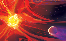
2021/02 – Artist view of the very young eruptive red dwarf AU Mic (left) and its newly discovered close-in planet (right) with the debris disc from which the planet was born in the background. © NASA-JPL/Caltech / Flares of Flury Poster
AU Mic planetary system #2
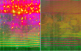
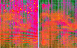
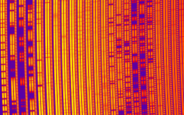
2021/02 – Portion of a SPIRou frame recorded for AU Mic. Each group of three vertical bars corresponds to one spectral order, covering a small region of the spectral domain. The two left-most vertical bars of each order contain the spectrum of AU Mic (in two orthogonal polarization states) whereas the right-most one contains a Fabry-Perot spectrum ensuring that velocimetric variation of the star can be monitored with a precision of a few m/s. The spectral lines (along with telluric lines from the Earth’s atmosphere) show up as darker horizontal bands in the image. These lines form a cosmic barcode encrypting information about AU Mic, its transiting planet and its magnetic activity that the SPIRou team was able to decode for the discovery outlined in this press release (©SPIRou team)
AU Mic planetary system #3
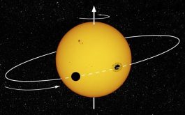
2021/02 – To better understand the formation of stars and their planets, it is key to find out whether the planet’s orbit is tilted to the equatorial plane of its host star. Our new results show that this tilt is small in the case of the giant planet of AU Mic, in agreement with recent models of planetary formation within protoplanetary discs.
© R Cardoso Reis (IA/UPorto) / Stellar activity can mimic misaligned exoplanets
AU Mic planetary system #4
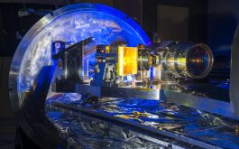
2021/02 – The new SPIRou spectrograph / spectropolarimeter, thanks to which our new results were secured, was installed at the Canada-France-Hawaii Telescope in 2018. SPIRou is a cryogenic instrument cooled down at -200°C that needs to be thermally regulated at the extreme stability level of 0.001°C to be able to detect planets like that of AU Mic. © SPIRou team / S Chastanet (CNRS / OMP)
AU Mic planetary system #5
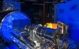
2021/02 – The new SPIRou spectrograph / spectropolarimeter, with its huge off-axis parabola (collimator) thanks to which our new results were secured, was installed at the Canada-France-Hawaii Telescope in 2018. SPIRou is a cryogenic instrument cooled down at -200°C that needs to be thermally regulated at the extreme stability level of 0.001°C to be able to detect planets like that of AU Mic. ©SPIRou team / S Chastanet (CNRS / OMP)
AU Mic planetary system #6
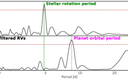
2021/02 – These curves depict the probability of a periodic oscillation to be present in the SPIRou radial velocity (RV) data, for wobble periods ranging from 1 to 50 days. Once the periodic RV signal induced by the activity of the rotating star (at a period of 4.86 day) is corrected for in the raw RV data (upper panel), the periodic signal induced by the newly-detected orbiting planet (at a period of 8.46 day) clearly shows up in the filtered RV data (lower panel) at a confidence level higher than 99.9%. ©B. Klein
2019
Stargazing with SPIRou #1
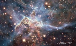
2019/02 – New forming worlds in the Carina Nebula similar to those SPIRou will observe, as seen in the visible and the infrared by the Hubble Space Telescope (© NASA)
Stargazing with SPIRou #2
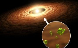
2019/02 – Artist view of the eruptive baby star EX Lupi and its protoplanetary disc in which silicate crystals like those found in comets can be created during outbursts of the central star. SPIRou will observe EX Lup simultaneously with TESS in June and July 2019 (© NASA/JPL)

Hunting exoplanets #1
2019/01 – SPIRou is expected to reveal an even more diverse world of planetary systems around nearby red dwarfs than that unveiled by Kepler around distant stars; see animated image at https://apod.nasa.gov/apod/ap151205.html (© Ethan Kruse)

Hunting exoplanets #2
2019/01 – Doppler effect used to measure velocities of stars, through the color shifts of their spectra. Stars moving away from us have red shifted spectra, whereas stars coming towards us have blue shifted spectra (© NASA)

Hunting exoplanets #3
2019/01 – Detecting exoplanet by measuring the wobbling velocities of stars with the “radial velocity method” based on the Doppler effect (©Las Cumbres Observatory)
Hunting exoplanets #4
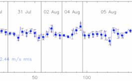
2019/01 – Velocity of Barnard’s star as a function of time for one set of SPIRou observations. This illustrates that SPIRou reaches a rms velocimetry precision of ~2 m/s when ignoring spectral regions where the relative depth of the lines from Earth’s atmosphere is larger than 50% (©SPIRou team)
Green light at CFHT #1
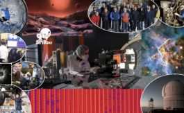
2019/01 – Illustrated summary of SPIRou activities in 2018 at CFHT (©SPIRou team)
Green light at CFHT #2
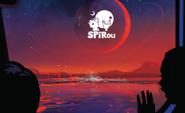
2019/01 – SPIRou is about to start its exploration of planetary systems around nearby red dwarfs, like the 7-planet system of Trappist-1 located 39 light-years away from us, and artistically pictured here as viewed from Trappist-1e, the 4th system Earth-like planet putatively located in the habitable zone of Trappist-1 (©NASA / SPIRou)
2018
SPIRou First Light at CFHT #1
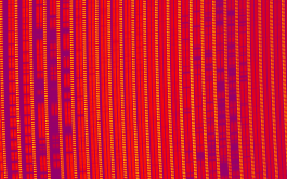
2018/04/24 – Portion of a SPIRou frame recorded for AD Leo. Each group of three vertical bars corresponds to one spectral order, covering a small region of the overall spectral domain. The two left-most vertical bars of each order contain the spectrum of AD Leo (in two polarization states) whereas the right-most one contains a Fabry-Perot spectrum ensuring that velocimetric variations of the star can be monitored with a precision of 1 m/s or better. The spectral lines of AD Leo (along with telluric lines from the Earth’s atmosphere) show up as darker horizontal bands in the image. These lines form a cosmic barcode encrypting information about AD Leo and its potential planets, that SPIRou will be able decipher. (©SPIRou team)
SPIRou First Light at CFHT #2
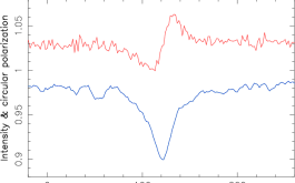
2018/04/24 – Circular polarization (red) in the spectral lines of AD Leo (blue) reveals the presence of magnetic fields at the surface of this active red dwarf (©J.-F. Donati – IRAP/OMP)
SPIRou First Light at CFHT #3
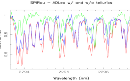
2018/04/24 – Small portion of the SPIRou spectrum of the active red dwarf AD Leo as observed (w/ telluric lines, red) and once the telluric spectrum (green) is removed (blue). This illustrates how critical telluric subtraction is to properly identify which lines can tell us some information about the observed star, and the planets potentially orbiting it. Located close to the reddest edge of the SPIRou spectrum, this window, containing a plethora of molecular lines, is key for detecting planets (©J.-F. Donati – IRAP/OMP)

SPIRou First Light at CFHT #4
2018/04/24 – Artist view of an active red dwarf similar to AD Leo, known for its huge flares (©Casey Reed/NASA)
First images with H4RG #1
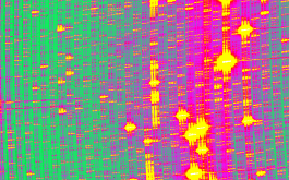
2018/04 – Portion of the SPIRou spectrum of a UNe hollow-cathode lamp as recorded by the new science-grade H4RG array (©SPIRou team)
First images with H4RG #2
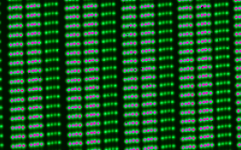
2018/04 – Zoom on Fabry-Perot lines, as recorded with SPIRou and its new science-grade H4RG array. Note that each spectrograph order (6 order portions are visible here) comes with three channels, two channels (left and middle) for recording the stellar spectrum (one channel for each of the two orthogonal polarization states) and one channel (right) for recording the reference FP spectrum (to track potential RV shifts within the spectrograph). FP spectra are recorded on all three channels during tests, in order to monitor the instrument RV precision, found to be better than 0.2 m/s rms on timescales of 24 hours (©SPIRou team)
First images with H4RG #3
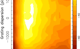
2018/04 – 2D map of the axial defocus (in µm) of the SPIRou spectra over the H4RG detector, as measured with a Hartmann mask (red / blue orders are on the left / right of the detector). Apart from an average defocus of 28 µm, this 2D map is compatible with what Zemax (optical design software) predicts for the axial chromatic defocus over the spectral domain (©SPIRou team)
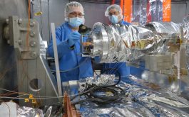
H4RG detector installation #1
2018/03 – Philippe Vallée (UdeM) and Greg Barrick (CFHT) install the H4RG science-grade detector on the SPIRou camera at CFHT (© S. Baratchart – OMP/IRAP)
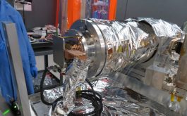
H4RG detector installation #2
2018/03 – The new H4RG science-grade detector and dedicated FPA mounted at the focus of the SPIRou camera (© S. Baratchart – OMP/IRAP)
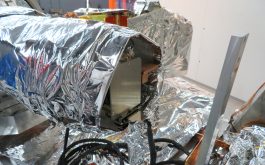
H4RG detector installation #3
2018/03 – Wrapping the H4RG detector and dedicated FPA with multi-layer insulation (MLI) (© S. Baratchart – OMP/IRAP)
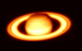
Cassegrain unit – First light #1
2018/03 – Saturn as viewed with the SPIRou near-IR (Raptor SWIR) guiding camera (© C. Moutou – CNRS/CFHT)
Cassegrain unit – First light #2
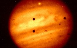
2018/03 – Jupiter as viewed with the SPIRou near-IR (Raptor SWIR) guiding camera. The two pinholes near the image centre are the main instrument entrance aperture and the alignement verification aperture (© C. Moutou – CNRS/CFHT)
Cassegrain unit – First light #3
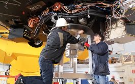
2018/03 – Sébastien Baratchart (IRAP/OMP) and Greg Barrick (CFHT) installing the SPIRou Cassegrain Unit at the Cassegrain focus of the CFH telescope (© S. Baratchart – OMP/IRAP)
Cassegrain unit – First light #4
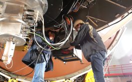
2018/03 – Installing the control electronic rack next to the SPIRou Cassegrain unit at the Cassegrain focus of the CFH Telescope (© S. Baratchart – OMP/IRAP)
Cassegrain unit – First light #5
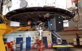
2018/03 – The SPIRou Cassegrain unit and control electronics installed at the Cassegrain focus of the 3.6m CFH Telescope (© S. Baratchart – OMP/IRAP)
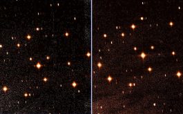
First Cryo-cycle completed #1
2018/03 – Comparison between hollow-cathode frames taken at IRAP / OMP (left) and at CFHT (right) (©SPIRou team)
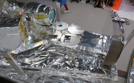
First Cryo-cycle completed #2
2018/03 – The spectrograph bench following the first cryogenic cycle at CFHT #1 (©S. Baratchart – OMP/IRAP)
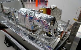
First Cryo-cycle completed #3
2018/03 – The spectrograph bench following the first cryogenic cycle at CFHT #2 (©S. Baratchart – OMP/IRAP)
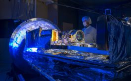
First cryo-cycle at CFHT #1
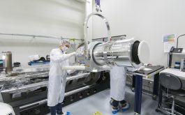
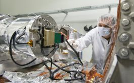
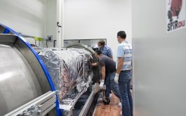
2018/02 – Overview of the fully-integrated SPIRou spectrograph with all optical components, before installing the active and passive shields (© S. Chastanet – CNRS/OMP)
First cryo-cycle at CFHT #2
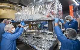
2018/02 – Installing the active and passive shields over the SPIRou bench, optical components and detector (© S. Chastanet – CNRS/OMP)
First cryo-cycle at CFHT #3
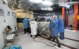
2018/02 – Closing the SPIRou vessel prior to the start of the first cryogenic cycle at CFHT (© S. Chastanet – CNRS/OMP)
First cryo-cycle at CFHT #4
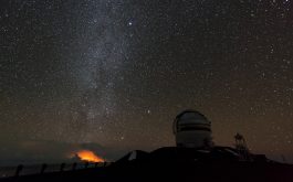
2018/02 – The Milky Way stretching from the distant lava flow (left) above the nearby Gemini North telescope as viewed from the CFH telescope (© S. Chastanet – CNRS/OMP)
First cryo-cycle at CFHT #5
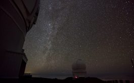
2018/02 – Starry night from the top of Maunakea, with the CFH telescope in the middle and the Gemini North telescope on the left (© S. Chastanet – CNRS/OMP)
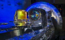
First cryo-cycle at CFHT #6
2018/02 – The SPIRou optical bench ready for the first cryogenic cycle at CFHT (© S. Chastanet – CNRS/OMP)
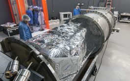
SPIRou comes back to life #1
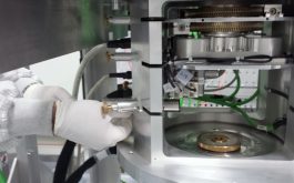
2018/02 – Opening the SPIRou vessel following the first vacuum test #1 (© S.Chastanet – CNRS/OMP)
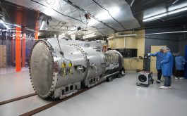
SPIRou comes back to life #2
2018/02 – Opening the SPIRou vessel following the first vacuum test #2 (© S.Chastanet – CNRS/OMP)
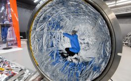
SPIRou comes back to life #3
2018/02 – Adjusting the multi-layer insulation inside the SPIRou vessel (© S. Chastanet – CNRS/OMP)
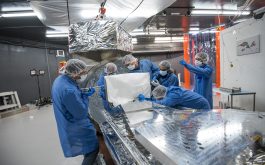
SPIRou comes back to life #4
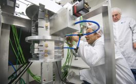
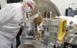
2018/02 – Installing the off-axis parabolic collimator on the SPIRou bench (© S. Chastanet – CNRS/OMP)
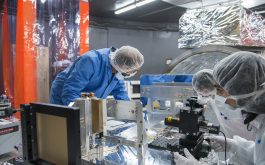
SPIRou comes back to life #5
2018/02 – Fine tuning the position of the SPIRou off-axis parabolic collimator (© S. Chastanet – CNRS/OMP)
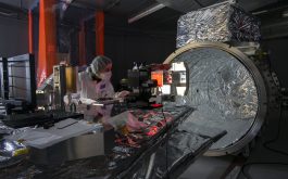
SPIRou comes back to life #6
2018/02 – Fine tuning the location and orientation of the pupil slicer on the SPIRou bench (©S. Chastanet – CNRS/OMP)
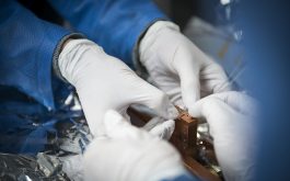
SPIRou comes back to life #7
2018/02 – Clamping the three SPIRou octagonal fibers of the pupil slicer on the ferrule separating the cold and warm sections of the vessel (© S. Chastanet – CNRS/OMP)
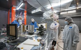
SPIRou comes back to life #8
2018/02 – Focusing the SPIRou spectrograph by adjusting the pupil slicer and the fold mirror versus the off-axis parabola #1 (© S. Chastanet -CNRS/OMP)
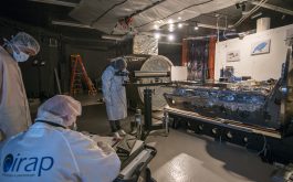
SPIRou comes back to life #9
2018/02 – Focusing the SPIRou spectrograph by adjusting the pupil slicer and the fold mirror versus the off-axis parabola #2 (© S. Chastanet -CNRS/OMP)
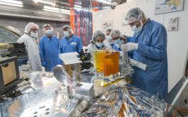
SPIRou comes back to life #10
2018/02 – Installing the triple-prism cross-disperser on the SPIRou optical bench #1 (© S. Chastanet – CNRS/OMP)
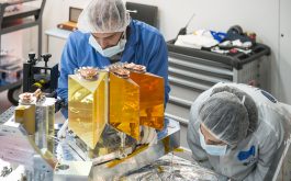
SPIRou comes back to life #11
2018/02 – Installing the triple-prism cross-disperser on the SPIRou optical bench #2 (© S. Chastanet – CNRS/OMP)
SPIRou comes back to life #12
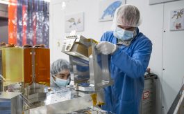
2018/02 – Installing the R2 echelle grating on the SPIRou optical bench #1 (© S. Chastanet – CNRS/OMP)
SPIRou comes back to life #13
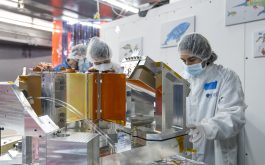
2018/02 – Installing the R2 echelle grating on the SPIRou optical bench #2 (© S. Chastanet – CNRS/OMP)
SPIRou comes back to life #14
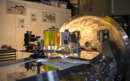
2018/02 – Overview of the SPIRou optical bench prior to the installation of the dioptric camera with the ESPaDOnS spectrograph in the background #1 (© S. Chastanet – CNRS/OMP)
SPIRou comes back to life #15
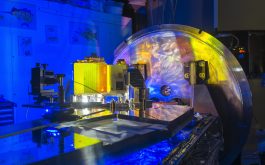
2018/02 – Overview of the SPIRou optical bench prior to the installation of the dioptric camera with the ESPaDOnS spectrograph in the background #2 (© S. Chastanet – CNRS/OMP)
SPIRou comes back to life #16
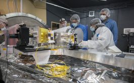
2018/02 – Installing the dioptric camera on the SPIRou optical bench (© S. Chastanet – CNRS/OMP)
SPIRou comes back to life #17
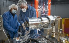
2018/02 – Installing the engineering H2RG detector at the focal plane of the SPIRou dioptric camera (© S. Chastanet – CNRS/OMP)
SPIRou comes back to life #18
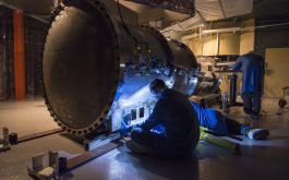
2018/02 – Adjusting the rails of the SPIRou cryogenic vessel (© S. Chastanet – CNRS/OMP)
SPIRou comes back to life #19
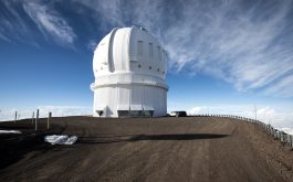
2018/02 – Leaving the CFH Telescope after a tough working day at 4200 m (© S. Chastanet – CNRS/OMP)
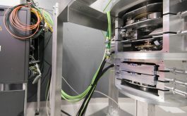
SPIRou comes back to life #20
2018/02 – The SPIRou Cassegrain unit following reassembly at CFHT (© S. Chastanet – CNRS/OMP)
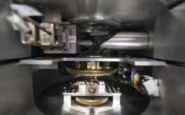
SPIRou comes back to life #21
2018/02 – Inner view of the upper Cassegrain unit (© S. Chastanet – CNRS/OMP)
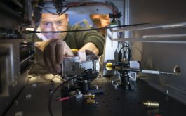
SPIRou comes back to life #22
2018/02 – Integrating and adjusting the SPIRou Calibration unit at CFHT (© S. Chastanet – CNRS/OMP)
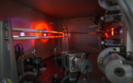
SPIRou comes back to life #23
2018/02 – Testing the hollow cathod lamps of the SPIRou Calibration unit (© S. Chastanet – CNRS/OMP)
SPIRou atop Maunakea #1
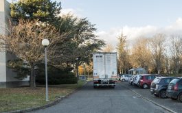
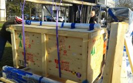
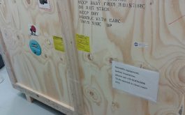
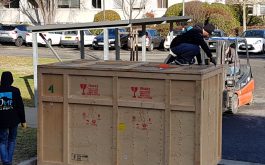
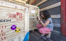
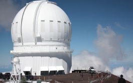
2018/01 – The first three SPIRou crates reach CFHT atop Maunakea on 2018 Jan 24 (©Z.Challita – IRAP/OMP)
SPIRou atop Maunakea #2
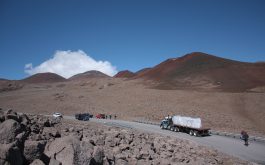
2018/01 – The truck transporting the SPIRou crates enters the paved Maunakea summit road leading to CFHT (©Z.Challita – IRAP/OMP)
SPIRou atop Maunakea #3
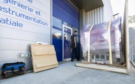
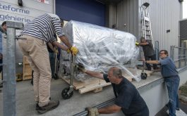
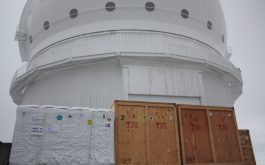
2018/01 – The second load of SPIRou crates is delivered at CFHT on Jan 25 (©Z.Challita – IRAP/OMP)
2017
Good-bye Toulouse #6
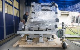
2017/12 – Packing the spectrograph internal support frame (©S.Chastanet – CNRS/OMP)
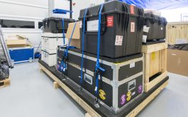
Good-bye Toulouse #7
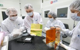
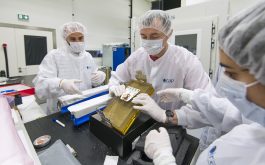
2017/12 – Crating of the SPIRou spectrograph optics and fibers (©S.Chastanet – CNRS/OMP)
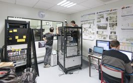
Good-bye Toulouse #8
2017/12 – The OHP team dismounting the calibration unit (©S.Chastanet – CNRS/OMP)

Good-bye Toulouse #10
2017/12 – Removing the prisms assembly from the SPIRou bench (©S.Chastanet – CNRS/OMP)
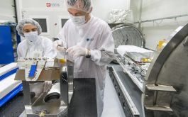
Good-bye Toulouse #13
2017/12 – Preparing the grating mount before disassembly (©S.Chastanet – CNRS/OMP)
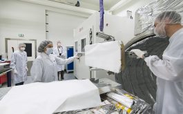
Good-bye Toulouse #14
2017/12 – Removing the off-axis parabola from the SPIRou bench (©S.Chastanet – CNRS/OMP)
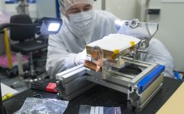
Good-bye Toulouse #15
2017/12 – Referencing the fold mirror before removing it from its mount (©S.Chastanet – CNRS/OMP)
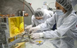
Good-bye Toulouse #18
2017/12 – Last positioning verifications before disassembly (©S.Chastanet – CNRS/OMP)
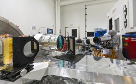
Good-bye Toulouse #19
2017/12 – Last alignment verifications before disassembly (©S.Chastanet – CNRS/OMP)
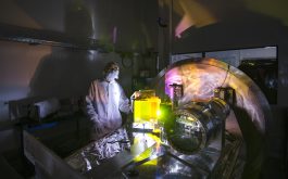
Good-bye Toulouse #20
2017/12 – SPIRou spectrograph bench before dismounting (©S.Chastanet – CNRS/OMP)
Good-bye Toulouse #22
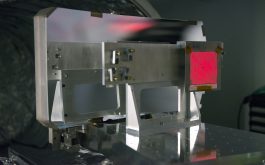
2017/12 – Last verification of the slicer before disassembly (©S.Chastanet – CNRS/OMP)
Good-bye Toulouse #23
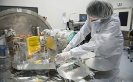
2017/12 – Dismounting the Hartmann mechanism before packing (©S.Chastanet – CNRS/OMP)
Good-bye Toulouse #24
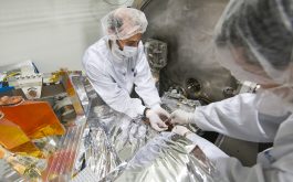
2017/12 – Removing the fibers from the SPIRou bench before packing (©S.Chastanet – CNRS/OMP)
Good-bye Toulouse #25
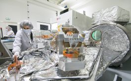
2017/12 – Preparation before removing the fiber from the SPIRou bench (©S.Chastanet – CNRS/OMP)
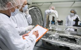
SPIRou pre-shipping visits #1
2017/12 – JY Duhoo from the SPIROU magazine takes notes and sketches for a new episode of the SPIRou comic strip adventures (©S.Chastanet – CNRS/OMP)
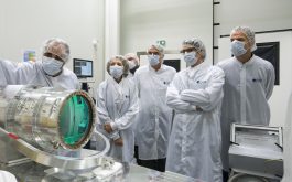
SPIRou pre-shipping visits #2
2017/12 – Driss Kouach details the main technical features of SPIRou for Elisabeth Borredon, Pierre Cabaré, Bertrand Monthubert and Sébastien Nadot (from left to right) (©S.Chastanet – CNRS/OMP)
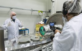
SPIRou pre-shipping visits #3
2017/12 – JF Donati outlines the main science goals of SPIRou and their implications in terms of instrument design to Pascal Varambon (©S.Chastanet – CNRS/OMP)
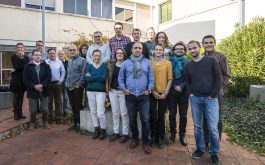
SPIRou goes to Hawaii #1
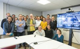
2017/11 – The happy SPIRou team and panel members, after green light was granted for shipping the instrument to Hawaii (©S.Chastanet – CNRS/OMP)
SPIRou goes to Hawaii #2
2017/11 – The SPIRou team and panel members, including Andy Sheinis and Greg Barrick from CFHT on the TV screen, who stayed up for 2 nights in a row to participate to the review via videoconference (©S.Chastanet – CNRS/OMP)
SPIRou goes to Hawaii #3
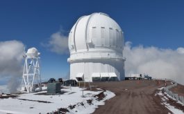
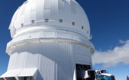
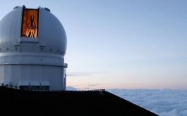
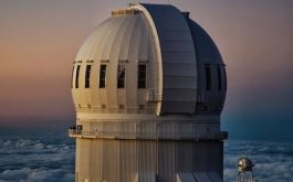
2017/11 – The Canada-France-Hawaii Telescope (CFHT) where SPIRou will be installed early next year (©CFHT)
SPIRou validation #1
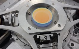
2017/11 – The ISU plate and mechanism thanks to which the image of the star can be centered on the instrument aperture with a precision better than 0.7 µm (©S.Chastanet – CNRS/OMP)
SPIRou validation #2
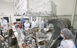
2017/11 – Opening the SPIRou spectrograph to improve the multi-layer insulation and the thermal stability between cycle #3 and cycle #4 (©S.Chastanet – CNRS/OMP)
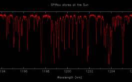
SPIRou stares at the Sun #2
2017/11 – Small portion of the infrared solar spectrum as recorded by SPIRou, dominated by telluric absorption lines from the Earth’s atmosphere, with a few spectral lines of the Sun hiding in the crowd (©J-F. Donati – IRAP/OMP)
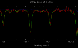
SPIRou stares at the Sun #3
2017/11 – An even smaller portion of the infrared solar spectrum as recorded by SPIRou, this time showing mostly solar lines and only a few telluric lines. The SPIRou spectrum (red) is compared to a reference spectral atlas of the Sun (green) and of the atmospheric spectrum (blue). This demonstrates in particular that SPIRou reaches a spectral resolving power of 70000 (©J-F. Donati – IRAP/OMP)
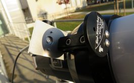
SPIRou stares at the Sun #4
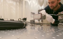
2017/11 – The fluoride optical fiber mounted on the side of the telescope, collecting light from the Sun through a small aperture and conveying it to SPIRou inside the clean room at IRAP / OMP (©Z.Challita – IRAP/OMP)
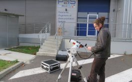
SPIRou stares at the Sun #5
2017/11 – Sacha Foschino from the UPS-IN-SPACE student association at Université de Toulouse Paul Sabatier, is participating to the experiment and setting up the solar telescope with its automatic tracking to be used for feeding SPIRou with light from the Sun (©Z.Challita – IRAP/OMP)
Second slicer #1
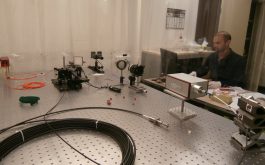
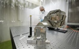
2017/10 – Testing the pupil slicer on the IRAP / OMP test bench (© S. Chastanet – CNRS/OMP)
Second slicer #2
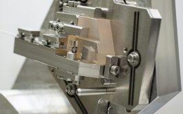
2017/10 – Internal view of the slicer miniature optical system (©S.Chastanet – CNRS/OMP)
Second slicer #3
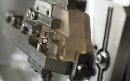
2017/10 – Light is injected through the 90-µm fibers positionned in v-grooves below the pupil slicing mirror, and comes out as a triple set of 4 slices formed on the mirror stack above the slicing mirror. (© S. Chastanet – CNRS/OMP)
Second slicer #4
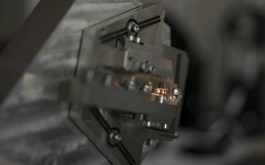
2017/10 – The collimator re-image the beam coming from the slicing mirror to the stack mirror (©S.Chastanet – CNRS/OMP)
Second slicer #5
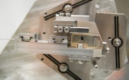
2017/10 – The second SPIRou pupil slicer during tests at IRAP / OMP (© S. Chastanet – CNRS/OMP)
SPIRou validates key velocimetric requirement #1
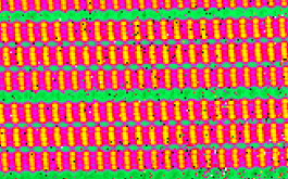
2017/07 – Spectral lines of Fabry Perot images collected with SPIRou, used to measure radial velocity drifts of the cryogenic spectrograph. The full Fabry Perot images contains more than ten thousands of such lines over the full spectral domain (©IRAP / OMP)
SPIRou validates key velocimetric requirement #2
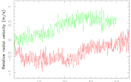
2017/07 – Drifts (in m/s) of the science spectrum with respect to the radial velocity reference in SPIRou for 2 of the long sequences of Fabry Perot images collected with SPIRou, demonstrating that SPIRou is stable to better than 0.25 m/s rms on periods of 24 hr. For comparison, 1 m/s on the detector corresponds to no more than one part in 2740 of a single pixel, or 6.6 nm, i.e., about the physical size of a complex protein molecule (©IRAP / OMP)

SPIRou validates key velocimetric requirement #3
2017/07 – Artist view of the 7 planets recently discovered around Trappist-1 (©NASA)
Perfect focus for SPIRou #1
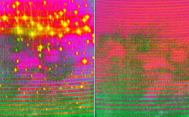
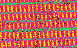
2017/06 – ThAr and Fabry Perot images secured with SPIRou perfectly focussed (© IRAP / OMP)
Perfect focus for SPIRou #2
2017/06 – Animated gif generated from Fabry Perot images alternately secured with the lower and upper Hartmann masks in the beam (© IRAP / OMP)
Perfect focus for SPIRou #3
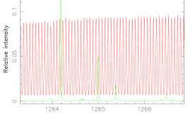
2017/06 – Tiny portion of wavelength calibrated ThAr (green) and Fabry Perot spectra around 1.26 µm, recorded with SPIRou and extracted with its data reduction software (© IRAP / OMP)
Second cryogenic cycle #1
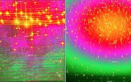
2017/05 – Spectrum of a Th-Ar hollow cathode lamp as measured with SPIRou during the second cycle (left) and as derived from simulations (right). A number of spectral orders / features are identified on the image (©J-F Donati – IRAP/OMP)
Second cryogenic cycle #2
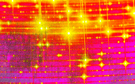
2017/05 – Comparison between images obtained in the first and second cycle.
The improvement in focus is quite obvious (©IRAP/OMP)
Second cryogenic cycle #3
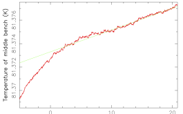
2017/05 – Bench temperature at mid distance from the 3 control points, over the last 25 hr of the second SPIRou cryogenic cycle (red curve). The rms thermal stability over the last 24 hr is found to be 1.6 mK (well within our specification of 3 mK, with a goal at 2 mK), and as low as 0.7 mK over the last 12 hr. The residual thermal drift over the last 20 hr (green line) is about 0.19 mK/h, with a rms residual dispersion about the drift of 0.13 Mk (©J-F Donati – IRAP/OMP)
Second cryogenic cycle #4
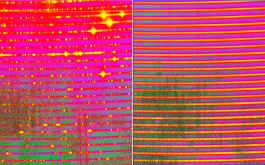
2017/05 – Close up views on SPIRou spectra, with the instrument fed with light from a U-Ne hollow cathode lamp (left) and Fabry-Perot etalon (right) (©IRAP/OMP)
Tribute to Pierre Soler #2
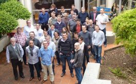
2017/05 – SPIRou Final Design Review at OMP, in April 2014 (©SPIRou – IRAP/OMP)
Another cooling cycle in progress #1
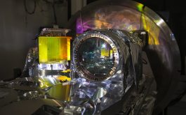
2017/04 – The full spectrograph ready for a new cooling cycle (©S.Chastanet – CNRS/OMP)
Another cooling cycle in progress #2
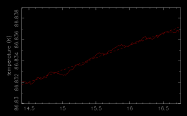
2017/04 – Temperature of the bench at mid distance from the 3 temperature control points, over the last 2.5 hr of the first SPIRou cryogenic cycle.
This curve shows a raw rms level of 1.6 mK over this time interval, a residual drift of 2.3 mK / h and a residual dispersion about the drift of 0.2 mK.
This temperature drift is mostly attributable to incoming heat from the detector and sidecar, kept unregulated for this first cycle (©J-F Donati – IRAP/OMP)
First SPIRou Lab images #1
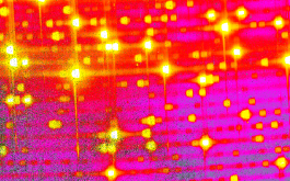
2017/03 – Zoom on a SPIRou spectrum of a Thorium-Argon hollow-cathode calibration lamp (©IRAP/OMP)
First SPIRou Lab images #2
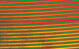
2017/03 – Zoom on a SPIRou spectrum of a Fabry-Perot calibration lamp (©IRAP/OMP)
First SPIRou Lab images #5
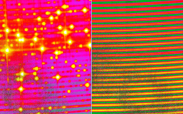
2017/03 – Zoom on a SPIRou spectrum of a Thorium-Argon hollow-cathode calibration lamp (at left) and of a Fabry-Perot calibration lamp (at right) (©IRAP/OMP)
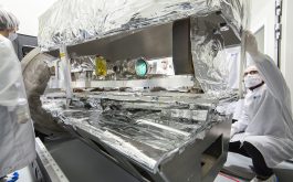
Cooling Cycle 2 at IRAP/OMP #1
2017/03 – Closing the SPIRou cryogenic spectrograph before cooling (© S. Chastanet – CNRS/OMP)
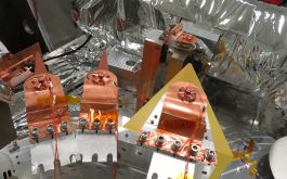
Cooling cycle 2 at IRAP/OMP #2
2017/03 – Cold straps and thermal probes bonded to the prisms and folding mirror (©V.Reshetov – NRC-H)
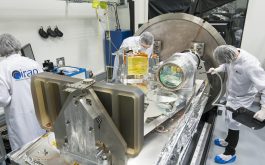
Cooling cycle 2 at IRAP/OMP #3
2017/03 – Preparation and cleaning of the spectrograph prior to closure (©S.Chastanet – CNRS/OMP)
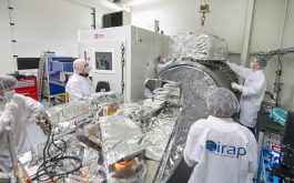
Cooling cycle 2 at IRAP/OMP #4
2017/03 – Crane-handling preparation of the active thermal screen prior to closure (©S.Chastanet – CNRS/OMP)
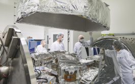
Cooling cycle 2 at IRAP/OMP #5
2017/03 – Crane-handling of the active thermal screen prior to closure (©S.Chastanet – CNRS/OMP)
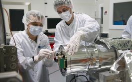
Detector delivery #1
2017/03 – The H2RG test detector mounted on the SPIRou camera (© S. Chastanet – CNRS/OMP)
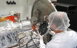
Detector delivery #2
2017/03 – Installing the H2RG detector at the rear of the camera (©Z.Challita – IRAP/OMP)
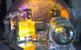
Camera delivery #2
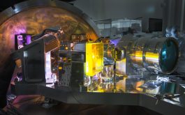
2017/02 – The spectrograph optics on the SPIRou cryogenic bench (©S. Chastanet – CNRS/OMP)
Camera delivery #1
2017/02 – The spectrograph optics on the SPIRou cryogenic bench (©S. Chastanet – CNRS/OMP)
Camera delivery #3
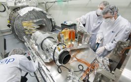
2017/02 – Connecting the camera with thermal straps and temperature sensors (©S.Chastanet – CNRS/OMP)
Camera delivery #4
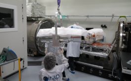
2017/02 – Installing the SPIRou camera on the optical bench (©D.Kouach – IRAP/OMP)
Slicer delivery #1
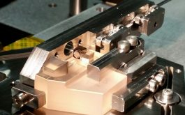
2017/01 – Internal view of the SPIRou pupil slicer during assembly. The Zerodur base on which the slicer components are installed is only about 5 cm in size (©Y.Micheau – IRAP/OMP)
Slicer delivery #2
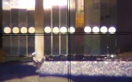
2017/01 – The 3 sets of 4 images (one set per fiber) aligned on the mirror stack, and acting as a 1.5-mm spectrograph slit (with the crosshair serving as an external aligning reference). Each thin mirror of the stack is tilted so as to redirect the pupil sector of each beam onto the spectrograph grating (© Winlight Optics)
Slicer delivery #3
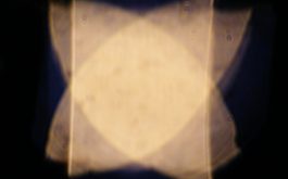
2017/01 – The pupil profile at the output of the pupil slicer, with the 12 overlapping pupil sectors (© Winlight Optics)
Slicer delivery #4
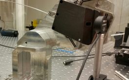
2017/01 – The slicer and dedicated mount during acceptance tests (© Y.Micheau, IRAP/OMP)
2016
Spectrograph alignment #1
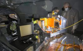
2016/12 – Aligning the spectrograph optics on the SPIRou optical bench (©S.Chastanet – CNRS/OMP)
Spectrograph alignment #2
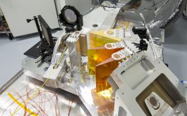
2016/12 – Overview of the SPIRou spectrograph in the alignment phase, within the P2IS clean room at IRAP/OMP (©S.Chastanet – CNRS/OMP)
Spectrograph alignment #3
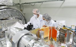
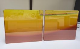
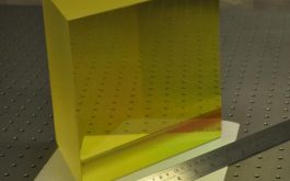
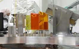
2016/12 – R2 échelle grating (right) and triple-prism cross-disperser (middle, the orange and yellow prisms are made of ZnSe and Infrasil respectively) in their dedicated mounts (©S.Chastanet – CNRS/OMP)
Spectrograph alignment #4
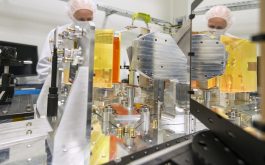
2016/12 – Reference masks (left), prism train and folding mirror in their mounts (middle), whose position on the optical bench is indexed with stepped brass pins (© S. Chastanet – CNRS/OMP)
Spectrograph alignment #5
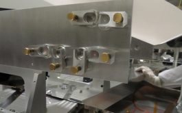
2016/12 – Reference mask with the pinholes on which the beam must be centred (©Z.Challita – IRAP/OMP)
Spectrograph alignment #6
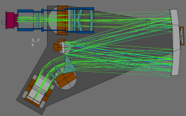
2016/12 – The SPIRou spectrograph optical design realised by Patrick Rabou from IPAG (©IPAG, Grenoble)
Optics integration #1
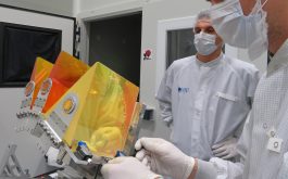
2016/11 – Integration of the prisms in their mount finalized at IRAP/OMP (©Z.Challita – IRAP/OMP)
Optics integration #2
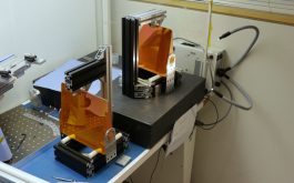
2016/11 – Bonding of the pucks and flexures on the two ZnSe prisms (©V.Reshetov – NRC-H)
Optics integration #3
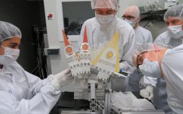
2016/11 – The three prisms of the cross-disperser, integrated on their mount (©M.Lacombe – IRAP/OMP)
Optics integration #4
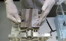
2016/11 – The folding mirror integrated on its mount. Several micrometric devices are used to set the mirror in its nominal position (©Z.Challita – IRAP/OMP)
Optics integration #5
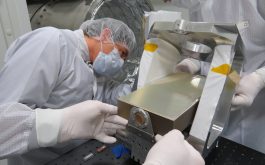
2016/11 – Grating integration, with the mount set upside down on the optical bench (©Z.Challita – IRAP/OMP)
Optics integration #6
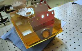
2016/11 – Bonding of the three sets of pucks & flexures on the Echelle grating (©V.Reshetov – NRC-H)

Cassegrain module alignment #1
2016/11 – Overview of the image stabilisation unit (ISU) structure (©S.Baratchart – IRAP/OMP)
Cassegrain module alignment #2
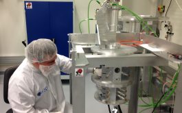
2016/11 – Optical alignment of the Cassegrain unit in the clean room at IRAP/OMP (©S.Baratchart – IRAP/OMP)
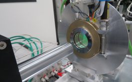
Cassegrain module alignment #4
2016/11 – One of the atmospheric dispersion corrector (ADC) in test (©L.Parès – IRAP/OMP)
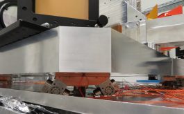
Cooling cycle at IRAP/OMP #2
2016/10 – View of the exapods under the optical bench (©Z.Challita – IRAP/OMP)
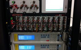
Cooling cycle at IRAP/OMP #4
2016/10 – The control command cabinet including the LakeShore controlers of the temperature sensors (©L.Saddlemyer – NRC-H)
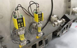
Cooling cycle at IRAP/OMP #5
2016/10 – The two vacuum gauges fixed on the cryostat (©L.Saddlemyer – NRC-H)
Cryostat cooling #1
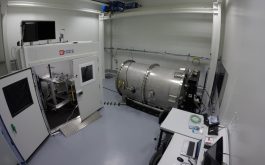
2016/10 – Cryostat in cooling phase at IRAP/P2IS plateform (note the SPIRou Cass module in the climatic chamber (©N.Striebig-CNRS/OMP)
Cryostat cooling #3
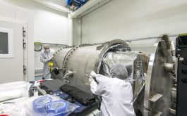
2016/10 – Closing the cryostat dewar by translating the movable cylindrical section
(©SChastanet-CNRS/OMP)
Camera integration and tests #1
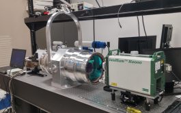
2016/10 – The science camera under integration and tests at UL and UdeM (©UL-UdeM)
Camera integration and tests #2
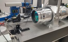
2016/10 – Rear side of the science camera where the detector will soon be mounted
(©UL-UdeM)
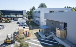
Spectro cryo-mech delivery #3
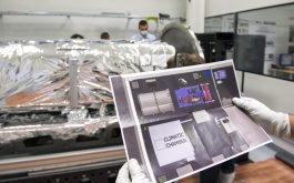
2016/09 – Overview of the crates at P2IS plateform (©SChastanet-CNRS/OMP)
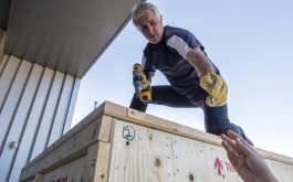
Spectro cryo-mech delivery #4
2016/09 – Crates opening with the help of René Dorignac from the GIS team based at Tarbes (©SChastanet-CNRS/OMP)
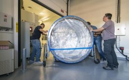
Spectro cryo-mech delivery #6
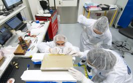
2016/09 – Installation of the first vessel section inside the clean room (©SChastanet-CNRS/OMP)
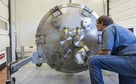
Spectro cryo-mech delivery #8
2016/09 – Cryostat cover inspection and cleaning (©SChastanet-CNRS/OMP)
Spectro cryo-mech delivery #9
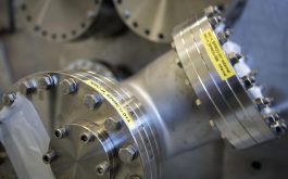
2016/09 – Hermetic feedthroughs of the cryostat cover (©SChastanet-CNRS/OMP)
Spectro cryo-mech delivery #11
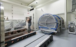
2016/09 – Cryostat installation inside the clean room (©SChastanet-CNRS/OMP)
Spectro cryo-mech delivery #12
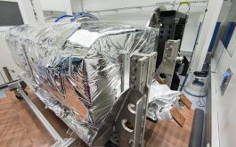
2016/09 – The optical bench covered with multi layer insulation (©SChastanet-CNRS/OMP)
Spectro cryo-mech delivery #15
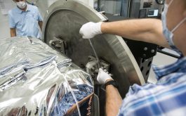
2016/09 – Optical bench screwing on the cryostat cover (©SChastanet-CNRS/OMP)
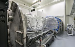
Spectro cryo-mech delivery #17
2016/09 – Overview of the complete cryostat in the IRAP/P2IS clean room, in Toulouse (©SChastanet-CNRS/OMP)
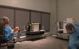
Off-axis Parabola metrology #1
2016/09 – Alignment step on one of the parabola clear aperture (©ZChallita-IRAP/OMP)
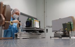
Off-axis Parabola metrology #2
2016/09 – Preparation of the metrology bench after Parabola integration on its mount (©ZChallita-IRAP/OMP)
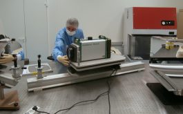
Off-axis Parabola metrology #3
2016/09 – Metrology on the Parabola before mounting (©ZChallita – IRAP/OMP)
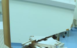
Off-axis Parabola integration #1
2016/08 – The off-axis Parabola integrated on its mount (©ZChallita-IRAP/OMP)
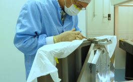
Off-axis Parabola integration #2
2016/08 – Bonding of the top flexure in Invar on the mounted Parabola (©ZChallita-IRAP/OMP)
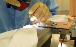
Off-axis Parabola integration #3
2016/08 – The Invar flexure bonding using fishing-lines as thickness gauges (©ACaillat-LAM)
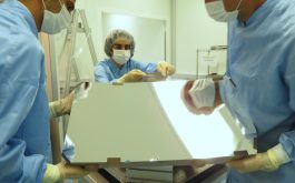
Off-axis Parabola integration #4
2016/08 – Off-axis Parabola integration on its mount at LAM (©ACaillat-LAM)
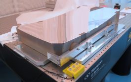
Off-axis Parabola integration #5
2016/08 – Zerodur pucks glued on the Parabola using a specific jig (©ZChallita-IRAP/OMP)
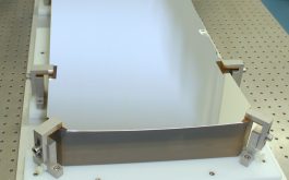
Off-axis Parabola delivery #1
2016/07 – The off-axis Parabola with its protected silver-coating (©Thales-SESO)
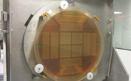
Off-axis Parabola delivery #2
2016/07 – The symmetrical lightweight structure of the Zerodur blank (©Thales-SESO)
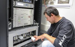
Calibration unit integration #1
2016/06 – Installation of the flat-field and hollow cathode lamps in the calibration unit (©Z.Challita – IRAP/OMP)

Calibration unit integration #2
2016/06 – Assembly and integration of the light source module of the calibration unit (©Z.Challita – IRAP/OMP)

Calibration unit integration #3
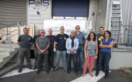
2016/06 – The OHP team in the P2IS control room following the integration @ IRAP of the SPIRou calibration unit (Z.Challita – IRAP/OMP)
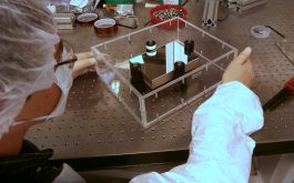
Zerodur folding flat mirror
2016/04 – Visual inspection of the Zerodur folding flat mirror, at NRC-H (©Z.Challita – IRAP/OMP)
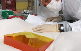
ZnSe prism
2016/04 – Visual inspection of one of the SPIRou ZnSe prism at NRC-H (©Z.Challita – IRAP/OMP)
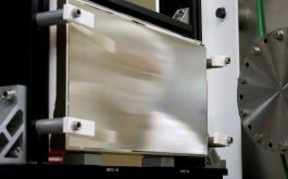
R2 Echelle grating #1
2016/04 – The SPIRou R2 échelle grating in Zerodur on its testing mount (©Z.Challita – IRAP/OMP)
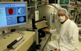
R2 Echelle grating #2
2016/04 – Wavefront error measurement of the SPIRou R2 échelle grating at NRC-H (©Z.Challita – IRAP/OMP)
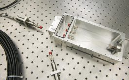
Fiber link section
2016/04 – The Cassegrain section of the fiber link, featuring three fibers in their aluminum box (©S.Chastanet – OMP)

Octagonal fibers
2016/04 – Octagonal fibers allowing high-enough scrambling performances at the entrance of the pupil slicer (©S.Chastanet – OMP)

Image Stabilization Unit #1
2016/03 – Image Stabilization Unit (ISU) of the SPIRou Cassegrain module, correcting for image motions caused by atmospheric turbulence and telescope instabilities (©S.Chastanet – OMP)
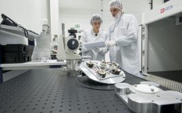
Image Stabilization Unit #2
2016/03 – Lab tests of the ISU in the P2IS clean room of IRAP / OMP, with the climatic chamber in the back (right side) (©S.Chastanet – OMP)

Cassegrain unit integration
2016/03 – Integration of the lower sections of the Cassegrain module, including the tip-tilt / guiding and the polarimetric units, in the P2IS clean room at IRAP / OMP (©S.Chastanet – OMP)
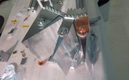
Dummy prisms
2016/03 – Optical mount of the double-pass triple-prism SPIRou cross-disperser, loaded with dummy optics (©S.Chastanet – OMP)
2015
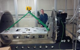
Internal Support Frame
2015/12 – The spectrograph internal support frame being integrated into the cryogenic vessel at NRC-H (©SPIRou team)
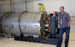
SPIRou cryostat #1
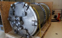
2015/09 – The SPIRou cryostat and its support structure next to Vlad Reshetov, the NRC-H engineer who designed it (©SPIRou team)
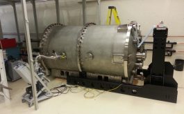
SPIRou cryostat #2
2015/09 – External support frame (ESF) assembled and positioned and cryostat uncrated and placed between the rails on blocks, awaiting rails (©SPIRou team)
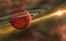
Hot Jupiters courting baby stars
2015/09 – Artist view of a newly born giant planet in the disc of a baby star ©NASA/JPL
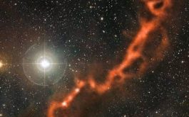
Taurus nursery
2015/09 – Formation of stars and their planets in the Taurus nursery as seen at millimeter wavelengths by the APEX telescope in Chile ©ESO/APEX
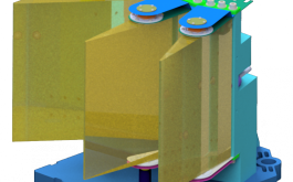
Trio Prisms
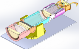
2015/08 – CAD View of the prisms onto their support to form the overall triple-prism-train cross-disperser of the SPIRou spectrograph (©SPIRou team)
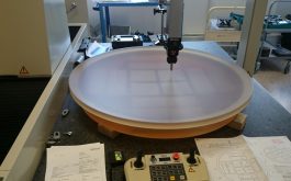
Off-axis parabola #1
2015/06 – Control of the SPIRou 880 mm diameter parent off-axis parabolic collimator at Thalès-SESO (©SPIRou team)
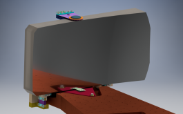
Off-axis parabola #2
2015/06 – Front CAD view of the SPIRou off-axis parabola in its dedicated stress-free mount (©SPIRou team)
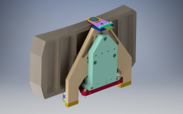
Off-axis parabola #3
2015/06 – Back CAD view of the SPIRou parabola in its dedicated stress-free mount (©SPIRou team)
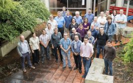
SPIRou passes the mid term review
2015/06 – SPIRou team and review panel at Observatoire Midi-Pyrénées ©SPIRou-Team
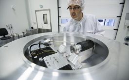
Cassegrain module
2015/06 – Integration of the upper section of the Cassegain module, interfacing SPIRou with the telescope and including calibration devices (©SPIRou team)

SPIRou guiding camera tested at CFHT
2015/04 – A portion of the Unicorn constellation
as captured by the SPIRou guiding camera, in which the image quality is about 0.6″ ©SPIRou-Team
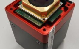
Raptor Camera
2015/04 – The SPIRou guiding camera is a commercial Raptor (OWL 640) camera providing the performances required for SPIRou in terms of field of view, sensitivity, read out noise and read out frequency (©SPIRou team)
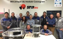
COMAT Team
2015/03 – The team of the supplier COMAT for the mechanical parts of the Cassegrain module (©SPIRou team)


